EE 582 (Physical Design Automation of VLSI Circuits and Systems)
Assignment 8
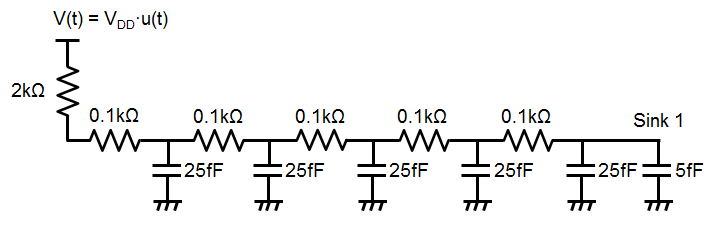
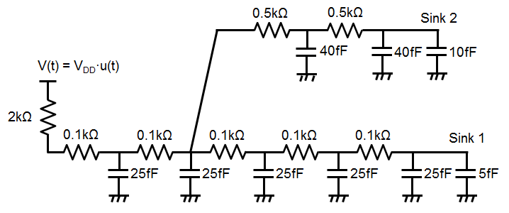
1. Elmore delay computation
Compute the delay at each sink using the Elmore delay model.
1.
2.
2. Wire modeling
The unit wire resistance is 2ohm/um and the unit wire capacitance is 0.4fF/um. The output resistance of the driver is 2kOhm and the input capacitance of the receiver is 5fF.
1. Each wire segment in the above figure is 200um and the net between the driver and the receiver is decomposed into ten wire segments. Therefore, the length of the net is 2,000um.
Convert the net into an RC network. (Use the pi-model to model each wire segment.)
2. Compute the delay from the driver to the sink using the Elmore delay model.
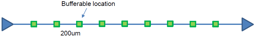
3. Delay computation
The delay of a buffer is 50ps. The wire characteristics are the same as those in Problem 2.

1. Each wire segment in the above figure is 200um. Convert the net into an RC network. (Use the pi-model to model each wire segment.)
2. Compute the delay from the driver to the sink using the Elmore delay model.