CptS 260 fourth programming project
Assigned: Nov 21, 2008
Due: Dec 12, 2008, 5PM
Turning in your assignment
When finished, submit your file named byteblt.s using the
the
Project turn-in link
at the left side of the CptS 260 web pages. (Click the link and
follow the directions.) You may turn in the assignment as many times as you like
before the deadline. Only the last will be graded. Please do not turn it in until the web page changes to say it is accepting uploads for assignment 4.
Introduction
One of the big advances in computer technology occurred in the
mid-1970's when the bit-mapped display was invented.
Because these displays typically displayed only black or white
for each pixel it was handy to be able to move a bit image of
arbitrary rectangular size to an arbitrary place on the display. To do this
efficiently, the
the so-called bitblt (pronounced "bit-blit") instruction was invented.
Bitblt was able to not only copy pixels but also combine source and
destination pixels using various, interesting, boolean functions.
There are two big issues in implementing bitblt for modern machines.
First, machines typically work much faster on words than on single bits so
implementations have to be designed to move full words whenever possible.
Second, the source and destination are allowed to overlap so implementations
have to be careful about what order they do the move.
With today's displays using multiple bytes per pixel, the importance
of bitblt has declined, but similar problems still arise when images are made
up multiple-byte pixels. For this project you will be creating a byteblt
procedure that moves (and combines) rectangular arrays of bytes (doing it
for bits is extra credit).
Problem Specification
Write a MIPS procedure byteblt
taking three arguments using the normal MIPS calling convention.
The first argument
is the address of a block specification for the source,
the second argument is the address of a block
specification for the destination, and the third is an integer indicating
how the final destination byte value is to be computed as
a boolean combination of the source
byte value and the original destination byte value as indicated below.
A block specification looks like
   int address   // byte address of the top left corner of the image
   int width     // width of the image in bytes
   int rownum    // row of top left corner of the block to copy (within the image)
   int nrows     // number of rows in the block (in bytes)
   int colnum    // column  of the top left corner of the block to copy (within the image)
   int ncols     // number of columns in the block
Note (12/10/08): the fields previously named
x, w, y, and h have been renamed to agree with addressing scheme
used in the example below.
The w and h
fields of the destination block specification are ignored. Assume
that memory addresses increase with increasing x
and y.
The possible function values (in the third argument) are:
   0 - source byte replaces the destination byte
   1 - source and destination bytes are combined using AND
   2 - source and destination bytes are combined using OR
   3 - source and destination bytes are combined using XOR
   4 - source and destination bytes are combined using IMPL:
       if the destination bit is 1 then use the source bit
       else use 0
Note (12/10/08): the behavior of function value 4 is the same as function value 1; my mistake.
Problem visualization
Here is an example: suppose we want to copy the 2x2 grey rectangular block from position
position (3,2) in image A to position (1,1) in image B. Here is what it looks like
beforehand:
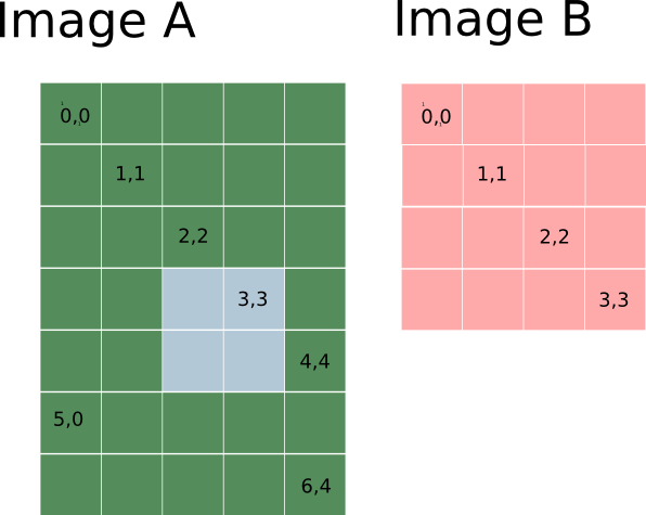
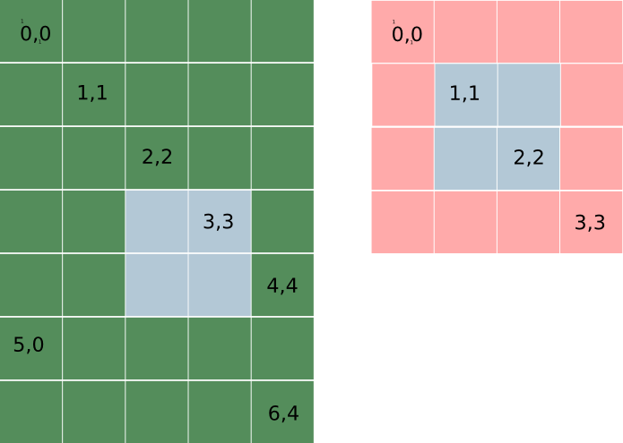
and here the the affected bytes of Image B have been marked in grey.
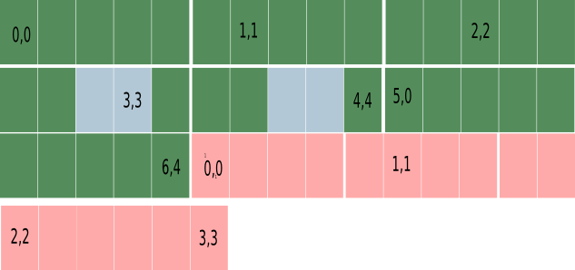
But neither image A nor image B is actually a rectangle in memory. Memory
is just a sequence of bytes, one after the other. So A and B in memory would
look something like this. The rows here are to be thought of as following
one another directly in memory. That is the address of the first cell of one row
is one more than the address of the last cell of the previous row. Also
note that image B does not have to directly follow
image A -- it could be anywhere.
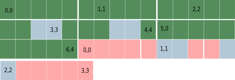
and here I've marked the bytes of image B that will be affected.
Implementation Hints
- Implement assuming no overlap and moving
a single byte at a time first. That will help you understand
the addressing calculations.
- By choosing the correct order for copying
it is possible to do each copy operation without decomposing the
region to be copied into sub-regions.
Fun
To make this more exciting there are two competitions associated with
this assignment.
- First, the MARS simulator has a "tool" that can be used to count
instructions
executed during a run of a program. There will be a 10 point bonus for whoever
is able to do a particular set of test cases in the fewest instructions.
- Second, whoever produces the solution with the smallest number of
instructions (statically) will get a 10 point bonus.
To receive either bonus your program must operate correctly on the
competition test cases as well as any other test case that the TA and
I decide to throw at it.
Over break I will post the competition test cases and create a web "scoreboard" where you can post your claimed
scores in both categories.
Decisions of the judges (Prof Hauser and TA Yan Sun) are final.
Grading
- Correctly functioning for non-overlapping source and destination is worth 30%
- Completely correct is worth another 50%.
- Proper commenting, formatting, etc. is worth 20%. Write your C-like pseudo code as
comments at the beginning of each function and use statements from the pseudo-code as
comments on the assembly code. Note that incorrect pseudo-code will be docked points
even if the assembly code
is correct -- incorrect documentation is extremely destructive to productivity.
There will also be a 10 point bonus if you correctly implement a
bitblt procedure (in addition to byteblt). Bitblt has the same spec as
byteblt but the x, y, w, and h
fields in the block specifications are counted
in bits rather than bytes. Assume a big-endian architecture -- bit 0 of a word
is the high-order bit.