Guide Contents | Introduction | How To: Windows, Mac OS X, Linux; Arduino Mini, Arduino BT, LilyPad Arduino; Xbee shield | Troubleshooting | Board | Environment
Introduction to the Arduino Board
Looking at the board from the top down, this is an outline of what you will see (parts of the board you might interact with in the course of normal use are highlighted):
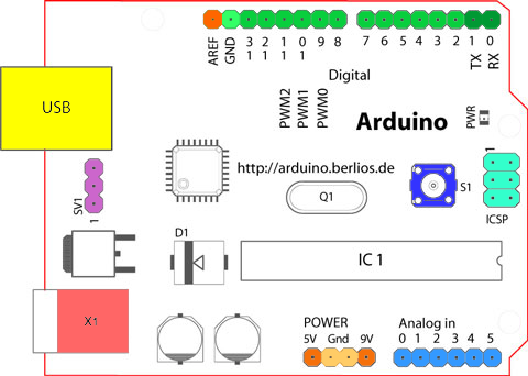
Starting clockwise from the top center:
- Analog Reference pin (orange)
- Digital Ground (light green)
- Digital Pins 2-13 (green)
- Digital Pins 0-1/Serial In/Out - TX/RX (dark green) - These pins cannot be used for digital i/o (digitalRead and digitalWrite) if you are also using serial communication (e.g. Serial.begin).
- Reset Button - S1 (dark blue)
- In-circuit Serial Programmer (blue-green)
- Analog In Pins 0-5 (light blue)
- Power and Ground Pins (power: orange, grounds: light orange)
- External Power Supply In (9-12VDC) - X1 (pink)
- Toggles External Power and USB Power (place jumper on two pins closest to desired supply) - SV1 (purple)
- USB (used for uploading sketches to the board and for serial communication between the board and the computer; can be used to power the board) (yellow)
The text of the Arduino getting started guide is licensed under a Creative Commons Attribution-ShareAlike 3.0 License and is based on the Arduino reference. Code samples in the guide are released into the public domain.